5.8. Plane Turbulent Channel Flow
This tutorial describes how to set up and run the test case of a turbulent flow in a plane channel geometry. We will learn how to use the split-form DG method to guarantee non-linear stability of the turbulent flow simulation. In a second step, we add the sub-grid scale (SGS) model of Smagorinsky combined with Van Driest type damping to run stable wall-bounded turbulent flows with explicit small scale dissipation. This tutorial is located in the folder tutorials/channel.
5.8.1. Flow description
The flow is calculated in a plane channel with half-height \(\delta=1\), streamwise (\(x\)-coordinate) length \(2\pi\) and span (\(z\)-coordinate) width \(\pi\) with periodic boundaries in the \(x\)- and \(z\)-directions as well as no-slip walls at the top and the bottom of the domain. As initial conditions, an analytical mean turbulent velocity profile a constant density of \(\rho=1\) is used. We superimpose sinus perturbations in the \(u\), \(v\) and \(w\) velocity components which lead to rapid production of turbulent flow structures. Since the wall friction would slow down the flow over time, a source term imposing a constant pressure gradient \(\frac{dp}{dx}=-1\) is added as a volume source. While the test case is incompressible in principle, we solve it here in a compressible setting. The chosen Mach number with respect to the bulk velocity in the field is \(Ma=0.1\), matching the Moser channel test case [26]. In this setting, the wall friction velocity \(\tau\) will always be equal to \(1\). We can define a Reynolds number based on the channel half-height and the wall friction velocity as \(Re_{\tau}=1/\nu\).
5.8.2. Build Configuration
FLEXI should be compiled with the channel preset using the following commands.
cmake -B build --preset channel
cmake --build build
5.8.3. Mesh Generation
We use a Cartesian mesh with \(4\) cells per direction for the tutorial. The mesh is stretched in the wall-normal direction to accommodate for the straining of the vortexes close to the wall. In case you want to generate other meshes, the parameter file for HOPR is included in the tutorial directory as parameter_hopr.ini. The default mesh uses \(4\) cells with a polynomial degree of \(N=5\), corresponding to a Large Eddy Simulation (LES) setup of \(24\) DOFs per direction.
5.8.4. Simulation Parameters
The simulation setup is defined in parameter_flexi.ini. In this tutorial, we are not interested in the flow visualization of the instantaneous state files. Instead, we post-process consecutive, instantaneous state files with the posti_channel_fft tool. As an output, we receive mean velocity and Reynolds stress profiles as well as turbulent energy spectra at different locations normal to the channel wall.
5.8.4.1. Interpolation / Discretization Parameters
! ============================================================ !
! SplitDG
! ============================================================ !
SplitDG       = PI     ! SplitDG formulation to be used: SD, MO, DU, KG, PI
In this tutorial, we use the split-form DG method to guarantee non-linear stability of the turbulent channel flow simulation. As already specified in the CMake options, the FLEXI_SPLIT_DG option has to be switched ON in combination with the FLEXI_NODETYPE=GAUSS-LOBATTO. FLEXI provides several distinct split-flux formulations. Therefore, a specific split flux formulation has to be chosen during runtime. In this tutorial, the pre-defined split-flux formulation by Pirozzoli [14] is used, which results in a kinetic energy preserving DG scheme.
5.8.4.2. Sub-Grid Scale Modeling
! ============================================================ !
! LES MODEL
! ============================================================ !
eddyViscType        = 0     ! Choose LES model, 1:Smagorinsky
VanDriest           = T     ! Van Driest damping for LES viscosity
CS                  = 0.11  ! Smagorinsky constant
PrSGS               = 0.6   ! turbulent Prandtl number
The eddyViscType defines the SGS model in use, with \(0\) corresponding to no model (implicit LES) and \(1\) the model by Smagorinsky [27]. The Smagorinsky constant CS is usually chosen around \(0.11\) for wall-bounded turbulent flows and the turbulent Prandtl number is commonly set to \(0.6\). To ensure the correct behavior of the eddy viscosity when approaching a wall, Van Driest-type damping has to be switched on.
5.8.5. Simulation and Results
We proceed by running the code with the following command.
flexi parameter_flexi.ini
If FLEXI was compiled with MPI support, it can also be run in parallel with the following command. Here, <NUM_PROCS> is an integer denoting the number of processes to be used in parallel.
mpirun -np <NUM_PROCS> flexi parameter_flexi.ini
Important
FLEXI uses an element-based domain decomposition approach for parallelization. Consequently, the minimum load per process is one grid element, i.e. do not use more processes than grid elements!
Once the simulation has completed, the generated state files can be post-processed via the posti_channel_fft tool which was build by the POSTI_CHANNEL_FFT CMake option. To run the post-processing, the standard command is
posti_channel_fft parameter_channel_fft.ini <State1 State2 ...>
The parameter_channel_fft.ini is provided in the tutorial folder. The selection of the specific State files to be used is left to the user. In this tutorial, we use all state files with a timestamp between \(t=10.0\) and \(t=15.0\). As an output you receive three files. One contains the mean velocity profiles as well as the Reynolds stress profiles while the other two files contain turbulent energy spectra. To visualize those files, you can run the python script plotChannelFFT.py, provided in the tools/testcases folder with the following command in your simulation directory.
python tools/testcases/plotChannelFFT.py -p <PROJECTNAME> -t <POSTITIME>
Here, <PROJECTNAME> specifies the project name specified in the parameter_flexi.ini file and <POSTITIME> is the timestamp of your output files from the posti_channel_fft tool.
5.8.5.1. Part I: Split-DG without Explicit LES Model
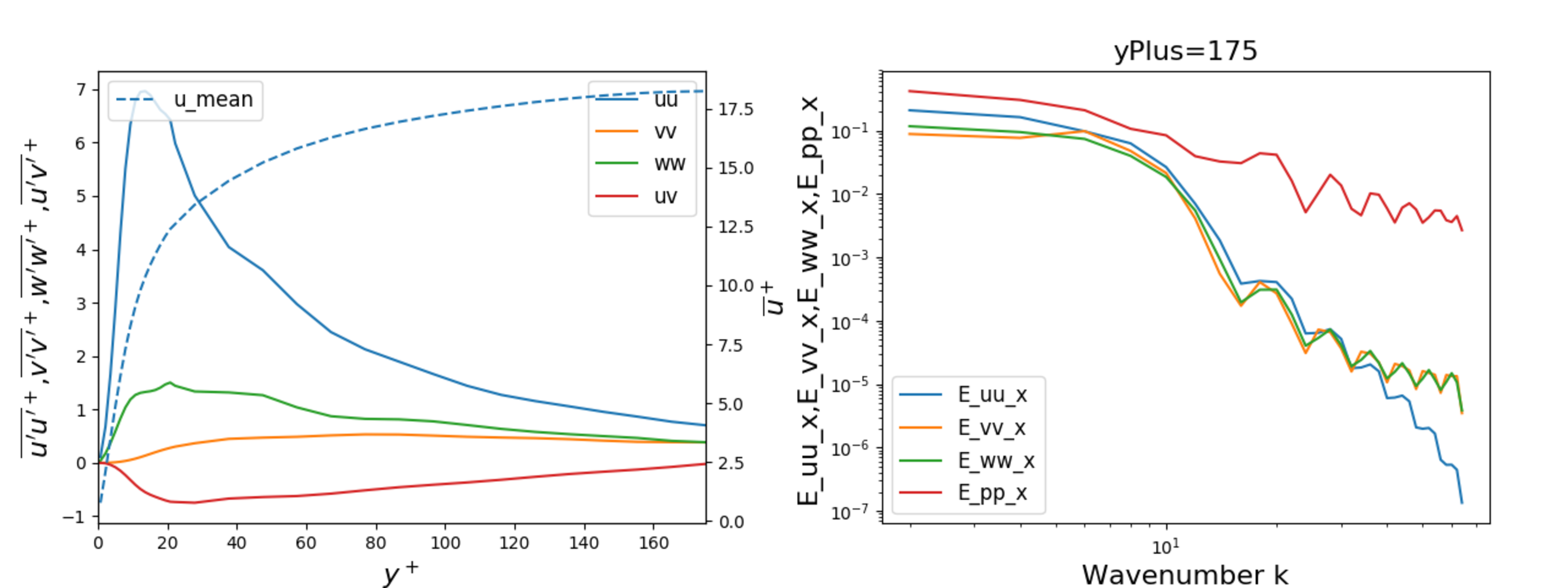
First, we run FLEXI without an SGS model. This configuration is called implicitly modeled LES (iLES), as no explicit sub-grid scale dissipation model is added. The resulting mean velocity and Reynolds stress profiles as well as turbulent energy spectra close to the center of the channel are given in Fig. 5.24.

Fig. 5.24 Mean velocity and Reynolds stress profiles (left) as well as turbulent energy spectra close to the center of the channel (right) of an implicit LES at \(Re_{\tau}=180\).
5.8.5.2. Part II: SplitDG with Explicit LES Model
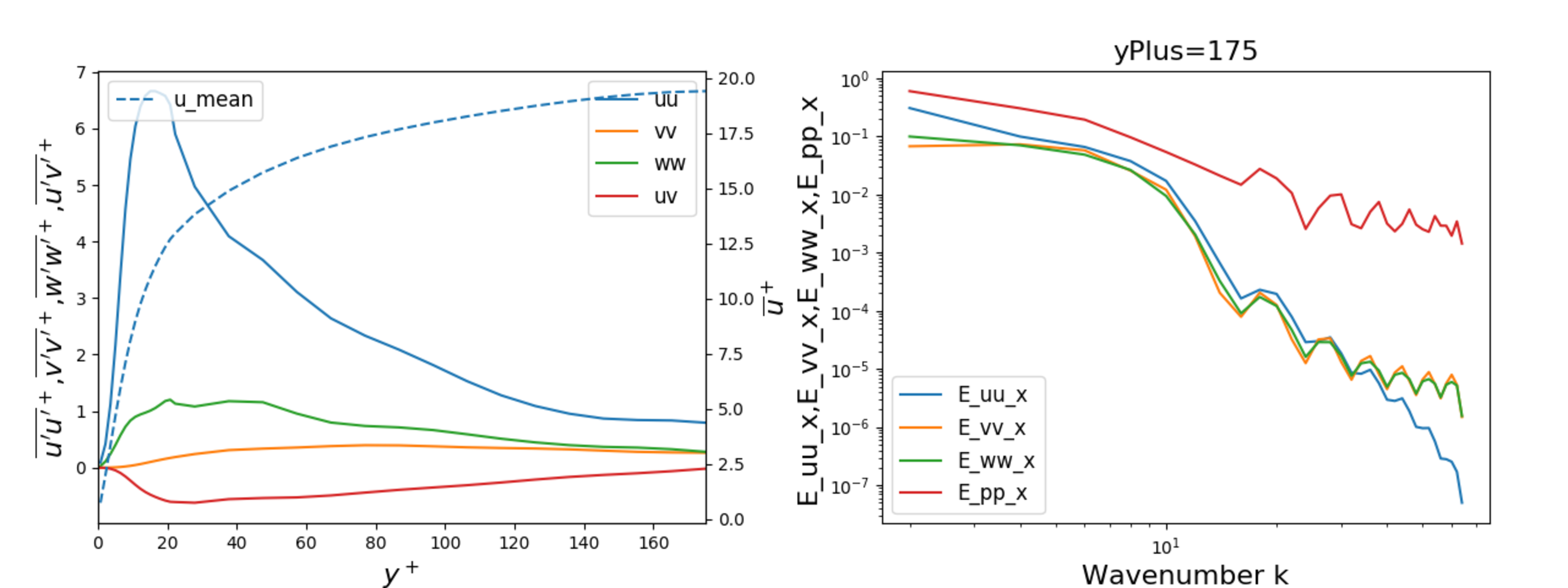
In a second step, we run FLEXI with the SGS model by Smagorinsky and Van Driest damping. These options need to be enabled in the parameter file as described above. The resulting mean velocity and Reynolds stress profiles as well as turbulent energy spectra close to the center of the channel are given in Fig. 5.25. In comparison to the previous simulation, you might recognize the effect of the explicit damping on the Reynolds stress profile \(\overline{u'u'}\), most evident close to the maximum. To further study the influence of Smagorinsky’s model, play around with the spatial resolution both in terms of grid resolution and the polynomial degree \(N\). You can also increase the Reynolds number to \(Re_{\tau}=395\) or \(Re_{\tau}=590\) and compare the results to DNS results from Moser et al. [26].

Fig. 5.25 Mean velocity and Reynolds stress profiles (left) as well as turbulent energy spectra close to the centre of the channel (right) of a LES with Smagorinsky’s model and van Driest damping at \(Re_{\tau}=180\).
5.8.6. Performance Improvements
FLEXI comes with some advanced optimizations in order to increase its computational efficiency for compute-intensive simulations. As these optimizations require user intervention, they are disabled by default and appear once the CMake flag FLEXI_PERFORMANCE=ON is set. The first option FLEXI_PERFORMANCE_OPTLIFT optimizes the computation of the parabolic terms of the applied equation system by omitting terms not relevant for the lifting procedure. However, POSTI is not available if this option is enabled.
5.8.6.1. Link-Time Optimization
The option FLEXI_PERFORMANCE_PGO=ON enable link-time optimization (LTO), sometimes called profile-guided optimization (PGO). For LTO/PGO, the executable is first instrumented with profiling tools by the compiler and then executed on a relatively simple test case. The generated profiling data can be used by the compiler to identify bottlenecks and hotspots in the code that cannot be identified from the static source code analysis. Consequently, the executable is compiled a second time using the gathered profiling data to perform these additional optimizations. In FLEXI, this two-step compilation works as follows. First, FLEXI is compiled with the following options.
cmake -B build -DFLEXI_PERFORMANCE=ON -DFLEXI_PERFORMANCE_OPTLIFT=ON -DFLEXI_PERFORMANCE_PGO=ON -DCMAKE_BUILD_TYPE=Profile
cmake --build build
For this first step, FLEXI is compiled with CMAKE_BUILD_TYPE=Profile build type in order to activate the profiling. Then, FLEXI has to be executed on a simple test case. Here, the freestream tutorial Section 5.2 provides a good starting step. Finally, FLEXI is compiled a second time, but this time with the build type set to CMAKE_BUILD_TYPE=Release.
cmake -B build -DFLEXI_PERFORMANCE=ON -DFLEXI_PERFORMANCE_OPTLIFT=ON -DFLEXI_PERFORMANCE_PGO=ON -DCMAKE_BUILD_TYPE=Release
cmake --build build
This setting incorporates the generated profiling data into the compilation process. Now, FLEXI can be executed as usual and should show a considerable performance improvement in comparison to the previous simulations.
Important
Link-Time Optimization (LTO)/Profile-Guided Optimization (PGO) is currently only supported for the GNU compiler. Furthermore, this two-step compilation process has to be performed each time either the code or the compile options, i.e. the FLEXI executable, are changed.